
API 682 Mechanical Seal Piping Plans: Complete Guide (Plan 01–76)
Why do mechanical seals need piping plans? In petrochemical and chemical services, media are often hot, volatile, abrasive or hazardous. The lubricating film between seal faces is only about half a micron thick — its stability decides whether a seal runs for years or fails in weeks. API 682 defines a set of standardized piping plans that use piping and auxiliary equipment (orifices, coolers, cyclone separators, reservoirs, buffer gas panels) to create a clean, cool and pressure-stable environment around the seal chamber. This guide walks through every piping plan from Plan 01 to Plan 76, grouped into single seals, quench and leakage collection, dual seals and gas seals, with a quick-selection table at the end.
1. What Problems Does a Piping Plan Solve?
Flushing means injecting or circulating liquid at the high-pressure side of a seal. Its five core purposes:
- Remove friction heat — heat generated between the seal faces must be carried away, or the film flashes and faces run dry;
- Lower fluid temperature — cooling increases the vapor margin (margin to boiling point) and reduces coking;
- Control seal chamber pressure — higher chamber pressure suppresses vaporization and stabilizes seal operation;
- Clean the fluid — solids and contaminants are filtered, separated or replaced by a clean external flush;
- Protect the atmospheric side — prevent drying, crystallization, coking or icing, and remove solids build-up.
2. Overview: Four Families at a Glance
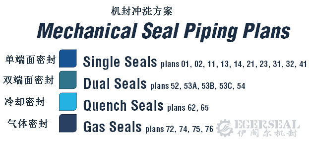
| Family | Plans | Typical Use |
|---|---|---|
| Single seals | 01, 02, 03, 11, 12, 13, 14, 21, 22, 23, 31, 32, 41 | Water, oils, hot water, solids-laden services |
| Quench & leakage collection | 51, 61, 62, 65A, 65B, 66A, 66B | Atmospheric-side anti-coking/crystallization, leak detection |
| Dual seals | 52, 53A, 53B, 53C, 54, 55 | Light hydrocarbons, hazardous media, zero-emission duty |
| Gas seals | 71, 72, 74, 75, 76 | Dry gas seals, buffer gas, leakage collection |
3. Single Seal Piping Plans (Plan 01–41)
Plan 01 — Internal Flush
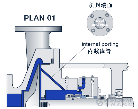
How it works: An internal porting channel routes fluid from the pump discharge area into the seal chamber — similar to Plan 11 but with no exposed piping.
Advantages: No external piping means no risk of freezing or crystallization blocking exposed lines, ideal for viscous, congealing fluids at moderate temperatures.
Where to use: Clean fluids at normal temperature; mostly single seals; not recommended on vertical pumps.
Maintenance notes: The flush should not impinge directly on the seal faces; ensure adequate circulation; avoid over-cooling. The internal passage can clog — avoid on dirty services.
Plan 02 — No Flush (Dead-Ended Seal Chamber)
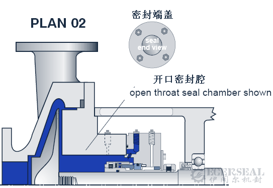
How it works: No piping plan at all — the seal chamber is dead-ended and relies on natural heat dissipation or a cooling/heating jacket on the chamber.
Where to use: Large-bore open seal chambers at ambient temperature; jacketed chambers in high-temperature service; clean fluids; dry-running vertical top-entry mixers and agitators; heating jackets for fluids that solidify at low temperature.
Maintenance notes: The process must have sufficient vapor margin — never use on flashing hydrocarbons; horizontal equipment must be self-venting; keep jacket coolant flowing in hot service; frequently combined with Plan 62 quench.
Plan 03 — Circulation by Seal Chamber Design
How it works: Circulation between the seal chamber and the pump is created by the design of the seal chamber itself (pumping devices, throat bushing geometry), with no external piping.
Where to use: Clean fluids at moderate temperature; pump models with specially designed seal chambers.
Plan 11 — Flush from Discharge (Industry Default)
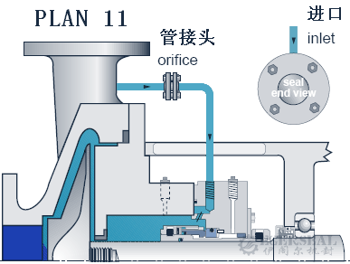
How it works: Fluid is taken from pump discharge and routed through an orifice and piping into the seal chamber — the default flush plan for single seals.
Benefits: Chamber cooling, venting of horizontal chambers, higher chamber pressure and larger vapor margin.
Where to use: Clean, non-polymerizing fluids; the vast majority of general-purpose chemical pumps.
Maintenance notes: The orifice bore is typically at least 0.125 in (3.2 mm), sized for the required flush flow; connect piping at the 12 o'clock position of the chamber for venting; orifice plugging is the classic failure mode — monitor pipe-end temperature to confirm flow.
Plan 12 — Flush with Strainer
How it works: Plan 11 plus an in-line strainer (usually Y-type) upstream, intercepting solids before they reach the seal chamber.
Where to use: Fluids with light particulate content or slight contamination.
Maintenance notes: Strainers need periodic blow-down; a rising pressure differential indicates a clogged screen.
Plan 13 — Flush to Suction (Vertical Pump Standard)
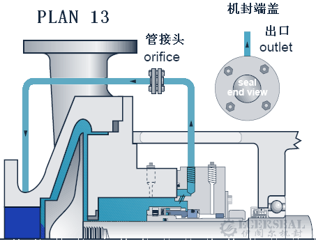
How it works: Fluid circulates from the seal chamber through an orifice back to pump suction — the reverse of Plan 11.
Benefits: Continuous venting of vertical pump seal chambers (gas trapped at the top would otherwise cause dry running) and chamber cooling.
Where to use: Vertical pumps; chamber pressure higher than suction pressure; moderately solids-laden fluids at moderate temperature, non-polymerizing.
Maintenance notes: Prime and vent before start-up; minimum orifice bore 0.125 in; check pipe-end temperature for plugging.
Plan 14 — Combined Discharge and Suction Flush
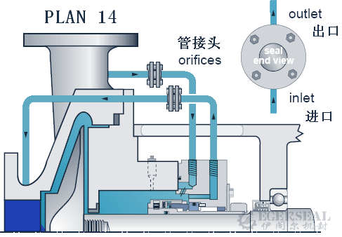
How it works: The combination of Plan 11 and Plan 13 — fluid enters the chamber from discharge and recirculates back to suction through orifices, giving continuous through-flow.
Where to use: Vertical pumps with clean, non-polymerizing fluids at moderate temperature, where both continuous venting and higher chamber pressure are wanted.
Plan 21 — Cooled Flush from Discharge
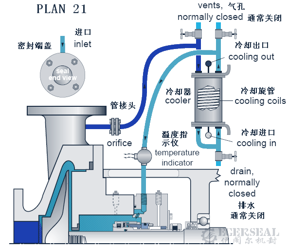
How it works: A seal cooler is inserted into the Plan 11 loop — flush fluid is cooled before entering the chamber, greatly increasing heat removal.
Where to use: Hot services, typically 80–177 °C (176–350 °F) hot water and clean hydrocarbons; reduces temperature and coking.
Maintenance notes: The cooler and piping must be self-venting at the highest point — open vents before start-up; monitor cooler inlet/outlet temperatures for fouling.
Plan 22 — Flush with Strainer and Cooler
How it works: Plan 21 plus a strainer, with the fluid filtered before it is cooled — the order matters, as it protects the cooler from fouling.
Where to use: Hot services with light solids content.
Plan 23 — Closed-Loop Circulation Through a Cooler (Hot Water Standard)
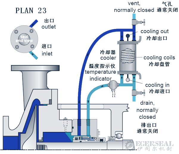
How it works: A pumping ring inside the seal chamber circulates fluid in a closed loop through a heat exchanger, isolated from the process fluid. The key difference from Plan 21: only a small loop of fluid is cooled, so the cooler runs at low duty with high efficiency.
Where to use: Hot hydrocarbons and boiler feed / hot water above 80 °C (180 °F) — the standard plan for hot water services; also improves the lubricity of water.
Maintenance notes: Piping should slope continuously toward the cooler (about 40 mm/m), with a high-point vent and low-point drain; keep total connection piping between seal and auxiliary system within about 5 m; use long-radius bends and avoid elbows to minimize friction losses.
Plan 31 — Cyclone (Abrasive) Separator
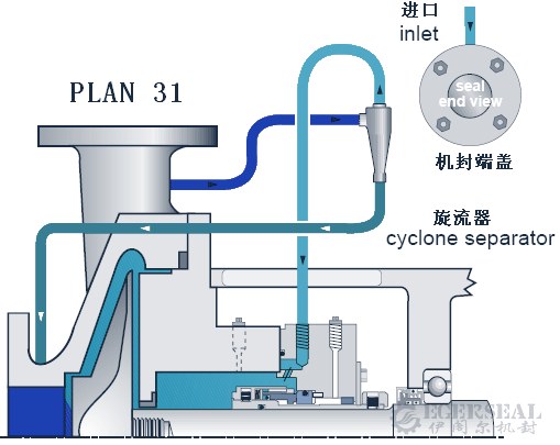
How it works: Discharge fluid passes through a cyclone separator: cleaned upper liquid goes to the seal chamber, solids-rich underflow returns to pump suction.
Where to use: Sandy or rust-contaminated water and fluids, non-polymerizing.
Maintenance notes: Works best when solids are significantly denser than the fluid (typically 2× specific gravity or more) and differential pressure is adequate; check the underflow port for erosion.
Plan 32 — External Flush
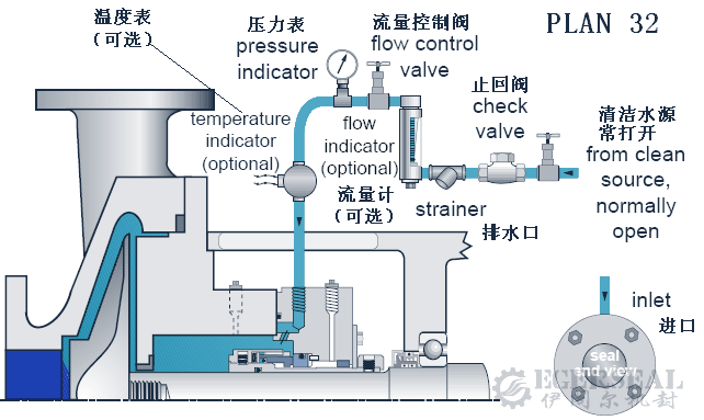
How it works: A clean external source injects flush fluid into the seal chamber, displacing the dirty process fluid. The line normally includes a check valve (back-flow prevention), flow indicator, strainer and isolation valve.
Where to use: Dirty or contaminated fluids, paper pulp, polymerizing and oxidizing fluids, high-temperature heavy oil pumps.
Maintenance notes: The flush fluid must be compatible with the process fluid — consider what happens when it mixes; injection pressure is typically 0.5–1 bar above chamber pressure; external flush dilutes the process fluid, so consumption cost must be evaluated.
Plan 41 — Cyclone Separator Plus Cooler
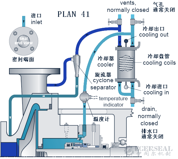
How it works: The combination of Plan 31 and Plan 21 — discharge fluid is separated by the cyclone, and the cleaned fluid is cooled before entering the chamber.
Where to use: Hot (typically below 177 °C / 350 °F) solids-laden services: boiler feed water, sandy hot water, contaminated hot hydrocarbons.
4. Quench and Leakage Collection Plans (Plan 51–66B)
These plans act on the atmospheric side of the seal and complement process-side flush plans.
Plan 51 — Dead-Ended Atmospheric Quench
How it works: The gland has a quench connection with a throttle, but no circulating piping — a dead-ended quench chamber collects condensing leakage.
Where to use: Services where leakage condenses and can be collected, usually with a throttle bushing.
Plan 61 — Quench Connection for Purchaser's Use
How it works: The gland only carries a spare quench/drain connection; whether to hook it up is the end user's decision, leaving room for future process changes.
Plan 62 — External Quench (Steam / Nitrogen / Water)
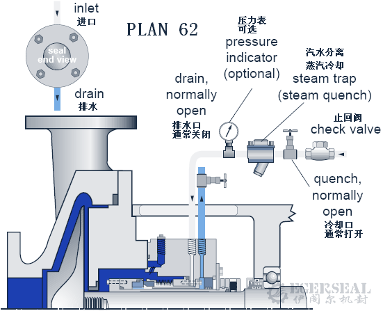
How it works: An external quench fluid — commonly steam, nitrogen or water — is introduced at the atmospheric side of the gland.
Benefits: Prevents coking (hot hydrocarbons), crystallization and salt deposition, atmospheric-side icing below 0 °C, and washes away build-up; normally combined with a small-clearance throttle bushing.
Maintenance notes: Quench inlet at the top of the gland, outlet/drain at the bottom; keep quench pressure around 0.2 bar (3 psi); steam service needs a steam trap, water service a check valve and orifice; regularly verify valve positions and line patency.
Plan 65A / 65B — Leakage Collection and Detection
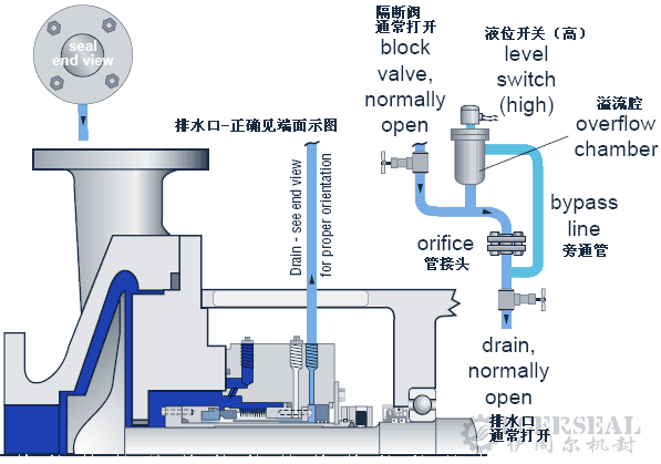
How it works: Atmospheric-side leakage drains into a riser fitted with a float level switch: Plan 65A alarms on excess instantaneous flow (failure detection by excess flow), Plan 65B alarms on cumulative leakage; an orifice of roughly 5 mm downstream routes normal leakage into the collection system.
Where to use: Single seals requiring leak monitoring — a safety indicator for the primary seal; can be used alone or with Plan 62.
Maintenance notes: Drain at the bottom of the gland with continuously downward-sloping piping; mount the orifice vertically; route the bypass below the orifice; heat-trace lines carrying congealing fluids; test the level switch periodically.
Plan 66A / 66B — External Leakage Detection
How it works: Plan 66A uses a throttle bushing and 66B an orifice plug to route leakage to an external detection arrangement, giving a clear indication of seal failure.
Where to use: Hazardous single-seal services with strict leakage monitoring requirements.
5. Dual Seal Piping Plans (Plan 52–55)
When the media are hazardous, toxic, volatile or zero process emission is required, dual seal arrangements introduce a barrier or buffer fluid between two seals.
Plan 52 — Tandem Seal with Unpressurized Buffer Reservoir
How it works: Tandem arrangement: inner seal is the primary seal, outer seal is the safety seal. The buffer reservoir is unpressurized (below seal chamber pressure); vapour from primary seal leakage maintains reservoir pressure and vents continuously to a vapour recovery or flare system.
Where to use: High-vapour-pressure fluids, light hydrocarbons, hazardous/toxic media, heat transfer fluids.
Character: Zero to very low process emission to atmosphere; outer seal failure releases process fluid — alarms are required.
Maintenance notes: Buffer fluid must be compatible with the process; monitor reservoir level and pressure — falling level indicates inner seal leakage, rising pressure indicates outer seal leakage.
Plan 53A — Pressurized Reservoir Barrier System
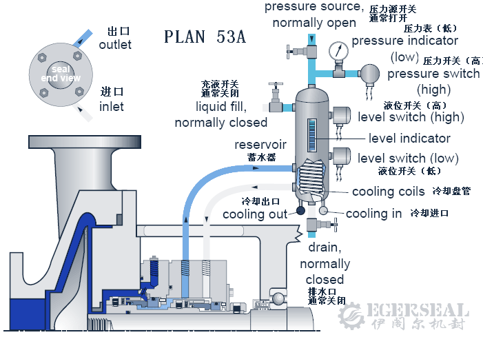
How it works: The barrier reservoir is pressurized by an external nitrogen pressure source to a pressure above the seal chamber (typically 10% higher, i.e. 1–3 bar differential). Barrier fluid circulates via the internal pumping ring and is cooled by coils in the reservoir. The barrier always pushes toward the process side, so process fluid cannot enter the barrier chamber — zero process emission.
Where to use: Pressurized dual seals; high-vapour-pressure fluids, light hydrocarbons, hazardous/toxic, dirty/corrosive/polymerizing media, heat transfer fluids.
Maintenance notes: Open all valves before start-up; keep nitrogen pressure stable (typically not exceeding 10–14 bar gauge); barrier fluid must be process-compatible; the level gauge is your diagnostic window — falling level means leakage to either the process or atmosphere side.
Plan 53B — Bladder Accumulator Barrier System
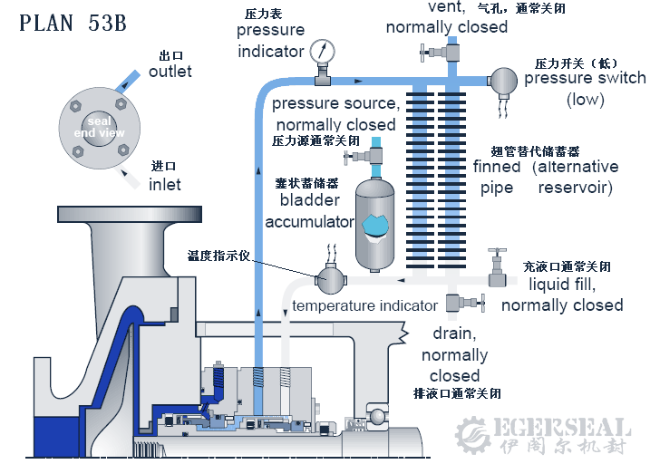
How it works: Pressure is supplied by a pre-charged bladder accumulator — nitrogen and barrier fluid are separated by the bladder, preventing gas dissolution into the fluid. Circulation is maintained by the pumping ring; heat is removed by a finned-tube (air-cooled) or water-cooled heat exchanger. Suited to higher pressures than 53A and where a continuous nitrogen supply is inconvenient.
Maintenance notes: Open all valves before start-up; monitor accumulator pressure and re-charge manually when it drops; bladder failure is the characteristic fault.
Plan 53C — Pressure-Tracking Piston Accumulator

How it works: A reference line feeds seal chamber pressure to the opposite side of a piston in the barrier unit, so barrier pressure automatically tracks chamber pressure at a constant differential. First choice where seal chamber pressure fluctuates strongly with operating conditions.
Maintenance notes: The reference line must stay clean and unobstructed; piston sticking destabilizes the differential; the level gauge shows leakage on both sides.
Plan 54 — Externally Pressurized Circulating Barrier System
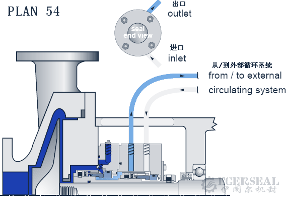
How it works: Barrier fluid is circulated by an external pump or pressurized system (mandatory when the seal has no pumping ring, e.g. agitators), with a heat exchanger removing heat and the reservoir pressure above the seal chamber.
Where to use: Pressurized dual seals on agitators/mixers, dirty abrasive media, high-temperature high-duty services.
Maintenance notes: Keep the circulation system permanently pressurized; the level gauge shows inner and outer seal leakage; the external pump is a single point of failure and needs scheduled maintenance.
Plan 55 — External Unpressurized Buffer System
How it works: Tandem arrangement like Plan 52, but buffer fluid comes from an external unpressurized system rather than a dedicated small reservoir; process leakage into the buffer side is collected and routed to recovery.
Where to use: High-vapour-pressure light hydrocarbons and hazardous media in tandem arrangement.
6. Gas Seal Plans (Plan 71–76)
Dry gas seals replace liquid barrier systems with nitrogen or another inert gas — common on high-speed pumps and hazardous services.
Plan 71 — Tap Connection for Purchaser's Use
How it works: A spare connection on the secondary containment seal chamber; hook-up is the user's decision.
Plan 72 — Low-Pressure Buffer Gas, Tandem Seal
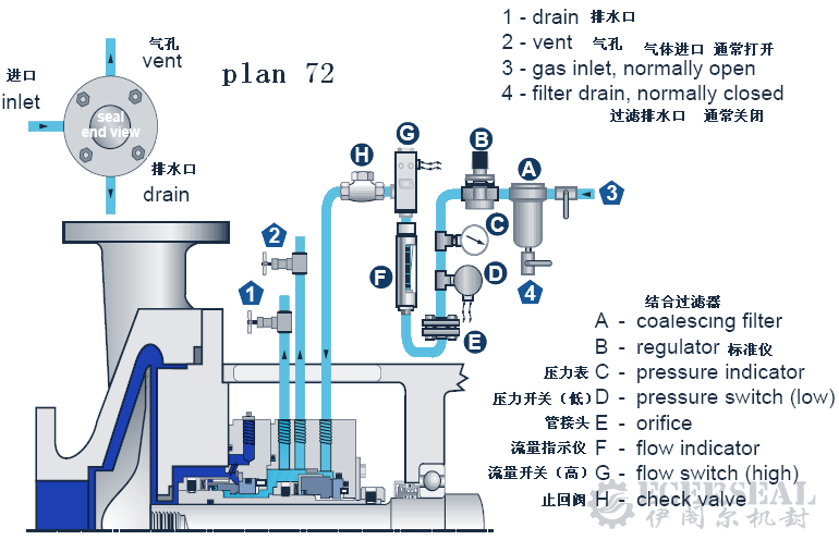
How it works: A tandem dry gas seal arrangement with low-pressure nitrogen buffer gas injected into the outer (safety) seal cavity — unpressurized relative to the chamber. Process vapour leaking past the primary seal is diluted by nitrogen and vented to flare or recovery through the vent connection.
Where to use: High-vapour-pressure liquids, light hydrocarbons, hazardous/toxic fluids; normally combined with Plan 75 or 76 leakage collection/vent systems.
Character: Zero to very low process emission; the buffer gas panel includes check valves, flow meters and high/low pressure switches.
Plan 74 — Pressurized Dual Gas Seal
How it works: Double-opposed dry gas seals with nitrogen barrier gas pressurized above the seal chamber pressure (typically 0.2–0.3 bar or more above). The barrier gas pushes toward the process side — zero process emission. The gas panel requires fine filtration (typically 5 micron), differential pressure gauges and flow meters.
Where to use: High-vapour-pressure liquids, light hydrocarbons, hazardous/toxic fluids; clean non-polymerizing services where a liquid barrier system is impractical.
Maintenance notes: Nitrogen must be clean and dry — drain filters regularly; primary seal failure shows up as a sudden flow/pressure change, so keep alarm devices calibrated.
Plan 75 — Leakage Collection for Condensing Leakage
How it works: Leakage from the secondary containment seal chamber first enters a liquid collection vessel (condensable components collected as liquid), while non-condensable gas vents to recovery or flare; the vessel is fitted with level switches and a pressure gauge.
Where to use: Fluids that condense at ambient temperature, low-vapour-pressure liquids; can be used alone or with Plan 72.
Plan 76 — Vent to Flare for Non-Condensing Leakage
How it works: Leakage from the containment seal chamber vents directly to flare or recovery — no liquid collection vessel, because the medium does not condense at ambient temperature.
Where to use: High-vapour-pressure light hydrocarbons such as methane-rich services; can be used alone or with Plan 72.
Plan 99 — Engineered Piping Plan
How it works: API 682 reserves Plan 99 for engineered piping arrangements outside the standard set — special cooling, special isolation or other custom requirements, to be specified in the technical agreement with piping, instrumentation and acceptance criteria.
7. Quick-Selection Table
| Service Condition | Recommended Plan | Notes |
|---|---|---|
| Clean fluid, ambient temperature (general) | Plan 11 | Industry default |
| Hot water / boiler feed above 80 °C | Plan 23 | Closed loop, most efficient cooling |
| Hot hydrocarbons 80–177 °C | Plan 21 / 23 | 21 for clean services, 23 preferred for hot hydrocarbons |
| Sandy / rust-contaminated fluid | Plan 31 / 41 | Cyclone separator; add cooler for hot services |
| Light particulates | Plan 12 / 22 | Strainer intercepts solids |
| Dirty fluids / pulp / polymerizing media | Plan 32 | External clean flush |
| Vertical pumps | Plan 13 / 14 | Continuous venting prevents dry running |
| Viscous, congealing fluids | Plan 01 / 02 | Avoids freezing of exposed piping |
| Atmospheric-side coking / crystallization / icing | Plan 62 | Steam / nitrogen / water quench |
| Light hydrocarbons, hazardous (trace leakage acceptable) | Plan 52 / 55 | Tandem seal with recovery |
| Light hydrocarbons, hazardous (zero emission) | Plan 53A/B/C / 54 | Pressurized barrier dual seals |
| Dual seals with fluctuating chamber pressure | Plan 53C | Automatic pressure tracking |
| Agitators (no pumping ring) | Plan 54 | External forced circulation |
| High-speed pumps / dry gas seal duty | Plan 72 / 74 | Nitrogen isolation |
Rule of thumb: Plan 11 for clean ambient duty, Plan 23 for hot water, 31 for sandy fluids, 32 for dirty services, 13 for vertical pumps, 52 for tandem recovery, the 53 family for zero emission, 62 quench against coking.
8. Frequently Asked Questions
What is a mechanical seal piping plan and why is flushing needed?
A piping plan (API 682) is a standardized configuration of piping and auxiliary equipment — orifices, coolers, cyclone separators, reservoirs — that controls the fluid environment of the seal chamber. Flushing removes friction heat, lowers fluid temperature, controls chamber pressure, cleans the fluid and protects the atmospheric side. The goal is always the same: keep a stable liquid film between the seal faces.
Which piping plan is used most often?
Plan 11 — flush from pump discharge through an orifice into the seal chamber. It combines cooling, venting and higher chamber pressure, and is the default choice for clean, non-polymerizing fluids on general-purpose centrifugal pumps.
What plan should a boiler feed water or hot water pump use?
For water above 80 °C (180 °F), Plan 23 is the standard: an internal pumping ring circulates a small closed loop of fluid through a cooler, delivering efficient cooling at low cooler duty and improving the lubricity of water.
How do I handle sandy or solids-laden media?
Use Plan 31: a cyclone separator routes clean fluid to the seal chamber and returns solids to pump suction. For hot solids-laden services upgrade to Plan 41 (separator plus cooler). For light particulates, Plan 12 (strainer plus orifice) is usually sufficient. Extremely dirty media such as paper pulp call for Plan 32 external flush.
How do I detect and fix a plugged orifice in the flush line?
Orifice plugging is the classic flush-system failure. Check the pipe-end temperature: if it drops toward ambient (normally it stays close to process temperature), flow has decreased and the orifice is probably plugged. Shut down, clean or replace the orifice, and add a strainer (Plan 12/22) if the medium is dirty.
Why are dual seal arrangements used for light hydrocarbons and hazardous media?
With a single seal, any leakage vents directly. Dual seals introduce a barrier or buffer fluid between two seals: Plan 52/55 tandem systems tolerate and recover trace leakage; Plan 53A/B/C and 54 pressurized barrier systems achieve zero process emission; dry gas seals use Plan 72/74 nitrogen isolation. The choice depends on the permitted emission level and how stable the seal chamber pressure is.
9. About EGERSEAL
Jiaxing Egerseal Mechanical Seal Co., Ltd. was founded in 2007 (formerly Jiashan Xincheng Seal Factory) and has nearly 20 years of experience in the design, manufacturing and repair of mechanical seals. Our product range covers pump seals, reactor vessel seals, marine seals and agitator seals, including engineered replacements for John Crane, EagleBurgmann, AESSEAL, Flowserve, Vulcan and Roten seals as well as seals for Flygt, Xylem and Grundfos pumps. We provide seal failure diagnosis, on-site repair and flush piping retrofits in line with API 682 requirements. 45% of our products are exported to 23 countries and regions. Contact us for a tailored flush-plan and seal selection for your specific media and operating conditions.